Photo © D. Winter 04/02/06 |
Saturday afternoon and Sunday morning saw the rest of the old frame
extension welds ground out to give a flat surface to mount the buffers
on.
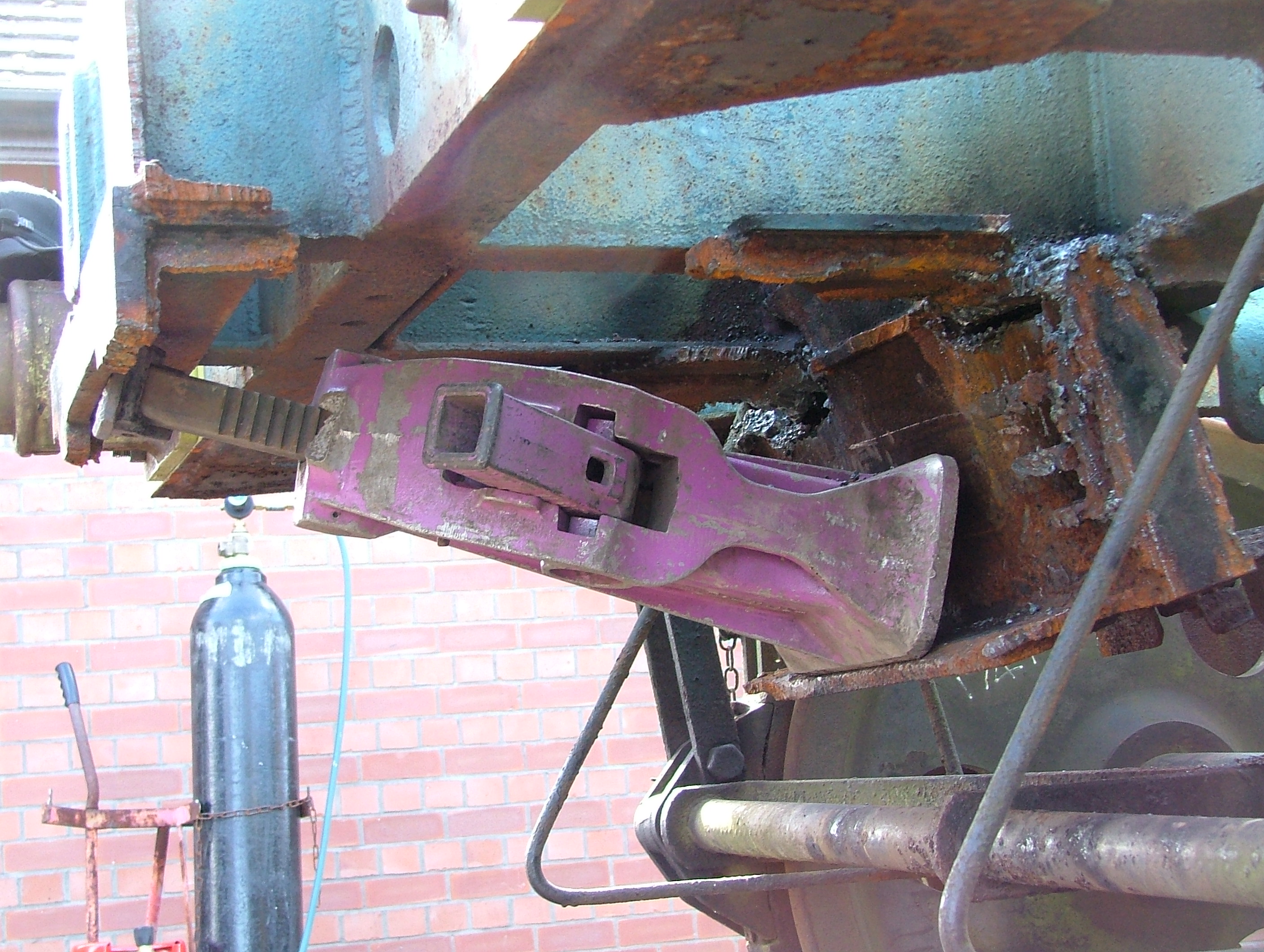
On the right hand photo you can see just how far the weld had
penetrated around the edge of the extension piece. The horizontal plate
below that is the remains of a gusset plate which formerly strengthened
the frame extension joint; these were removed by hammer and chisel. |

Photo © P. Hetherington 05/02/06 |

Photo © P. Hetherington 05/02/06 |

Photo © P. Hetherington 05/02/06 |

Photo © P. Hetherington 05/02/06 |

Photo © P. Hetherington 05/02/06 |
Shawn then prepared both the backs of the buffers and the wagon
headstock for painting, and applied some lovely green primer to
both surfaces (above).
Meanwhile, I tackled the glamorous job of cleaning up the bolts -
the photo on the left being included here mainly for its artistic
qualities.
Finally, we re-fitted the two buffers; the right hand photo shows me
tightening up the last nut. Another job done! |

Photo © S. Sanders 05/02/06 |
A change of scenery! The double slips which were originally laid back
in May 2005 were completed this week following delivery of the missing
components, and the Permanent Way department wasted no time in shunting
the yard to retrieve a couple of coaches which are expected to leave the
railway shortly. Most notable amongst these was the LMS-designed 12-wheeled
sleeping car M380M, because the Palbrick would have been blocking this
in. So we got the buffers back on in the nick of time! Thanks to the
good efforts of Nick and the p.way lads, the Palbrick has again been
left accessible, so work can continue, but we now have a Palvan for
company instead of - er - whatever it was before!

Photo © P. Hetherington 12/02/06 |
Back in January I'd started cutting the south end Freightliner
dragbox, but hadn't got very far before the oxygen ran out. After
messing about with buffers for a few weeks, I resumed this task and
chopped out a sizeable chunk from the left hand side. |

Photo © P. Hetherington 12/02/06 |

Photo © P. Hetherington 12/02/06 |
Next I continued with the remaining portion of the left hand side,
but first I had to burn off the nuts holding on the angled plate shown
on the left. This allowed access to cut the three corner gussets from
inside the old dragbox, and was certainly easier than cutting the
extra plate (which is what I'd done at the north end). |

Photo © P. Hetherington 12/02/06 |

Photo © P. Hetherington 12/02/06 |
Shawn, meanwhile, returned to the rather slow task of cutting
and grinding off the remnants of the north end Freightliner dragbox.
Once again we were impressed by the quality of the original weld;
unfortunately this meant that it didn't come off easily! |

Photo © P. Hetherington 12/02/06 |
| Back at the south end, and on something of a roll, I sliced another
hefty chunk off, this time from the east side. By which time it was dark!
|

Photo © P. Hetherington 12/02/06 |
To be continued... |

Photo © P. Hetherington 12/03/06 |
Continuing where he left off, Shawn is seen here contemplating
his next move. The object of his attentions is the plate shown in
the right hand photograph, one of the last remnants of the north
end Freightliner coupling. In order to improve access to this area
we first removed the metal strap shown in the left hand photograph;
these are designed to catch the brake rigging if it falls off. |

Photo © P. Hetherington 12/03/06 |

Photo © P. Hetherington 12/03/06 |
Meanwhile, I tackled the 'bigger stuff' at the south end; these
photos show the demise of another portion of the Freightliner
dragbox. |

Photo © P. Hetherington 12/03/06 |

Photo © S. Sanders 12/03/06 |
I then turned my attention back to the 'inside' portion of the
Freightliner dragbox, and sliced out another hefty chunk. Incidently,
each of these side pieces has taken a considerable time to cut due to
the three thick gussets inside, not to mention the obvious access
difficulties. |

Photo © P. Hetherington 12/03/06 |

Photo © P. Hetherington 12/03/06 |
Back at the north end, Shawn carefully ground around the edges
of the scrap plate to remove the majority of the welds holding it on,
and then finished off with a hammer and chisel (and crowbar!) until
- eventually - it came off. New gusset plates will be needed to
strengthen these joints - four in total. |

Photo © P. Hetherington 12/03/06 |

Photo © P. Hetherington 18/03/06 |
The first job today was to cut off the bottom corner of the
inner portion of the east side of the south end Freightliner
dragbox. These two photos give some idea of its construction. |

Photo © P. Hetherington 18/03/06 |
| This gave access to the three nuts and bolts holding this
piece onto the inside of the dragbox. This piece originally
formed the inside wall of the dragbox, keeping the rubber pads
in position. |

Photo © P. Hetherington 18/03/06 |
At the north end I'd generally left these bolts in situ and
cut the steel plate, but at the south end I've either unbolted
or cut the bolts, which has turned out to be easier. In this case,
as you can see, I had to cut the nuts off as they wouldn't budge,
even with heat. |

Photo © P. Hetherington 18/03/06 |
This gave access to cut the three gusset plates in the inside
corner of the upper portion of the side plate, and allowed me to
cut off the rest of the side plate, leaving just the thick central
plate and the top plates to remove at this end. |

Photo © P. Hetherington 18/03/06 |

Photo © P. Hetherington 25/03/06 |
Not a great deal of obvious progress this weekend. It took quite
a long time (and quite a bit of heat) to dismantle the south end
coupling hook to gain access to the inside of the original
dragbox.
These photos show the dragbox from underneath, with the drawhook
removed. On the left hand photo the frame extension is at the
bottom of the picture, with the original headstock in the centre.
Above that are two angled plates which the drawhook fits through;
these are not original and are too close together for re-mounting
the drawhook once the frame extension is removed, as well as not
giving enough depth. On the right hand photo you can just see
where the equivalent plates used to be prior to the Freightliner
alterations. |

Photo © P. Hetherington 25/03/06 |

Photo © P. Hetherington 25/03/06 |
Having removed the drawhook, I then managed to complete one cut
along the top plate 'behind' the thick central plate (left, seen
from below), and cut out two sections of top plate 'in front of'
the central plate (right, seen from above), at which point the
oxygen ran out. Not, it must be said, for the
first time!
I then had to put the original drawhook back together so that the
wagon remains mobile; at least next time it should come apart more
easily! |

Photo © P. Hetherington 25/03/06 |

Photo © P. Hetherington (probably) 16/04/06 |
Most of Sunday was spent completing the cutting of the thick
vertical plate from the south end Freightliner coupling. Rather than
struggle with bars and sledgehammers as at the north end, Shawn hit
on the idea of using a duff jack between the thick plate and the
remaining portion of the frame extension. This certainly made the
job quicker, though it still took a while. But eventually, it came
off. |

Photo © P. Hetherington 17/04/06 |

Photo © P. Hetherington 17/04/06 |
This still left a remnant of the thick plate above the frame
section on each side of the original dragbox, and as we didn't think
grinding these bits out was likely to work, I decided to have a go
at them with the cutting torch. Since the remnant was essentially
separate from the underframe, the heat didn't penetrate the frame and
it was possible to make quite a neat job. I'll have to do the same
at the north end in due course. |

Photo © P. Hetherington 17/04/06 |

Photo © P. Hetherington 17/04/06 |
The two prongs at the south (non-tensioning) end had been annoying
me for a while, so I straightened them using a handy Grampus wagon as
a vertical reference line. Actually after I took this photo I decided that the
nearest one still wasn't quite right so I straightened it a bit more. |

Photo © P. Hetherington 17/04/06 |

Photo © P. Hetherington 17/04/06 |
Having done that, I decided that it was time to tackle the
coupling hooks. A couple of swift cuts soon saw to the first one - and
so I cut off the north end hook for good measure. These hooks will be
re-instated in their original position below the headstock, for which
new mounting plates will be needed.
Flushed with success at cleaning up the inside of the original
dragbox, I decided to try the same technique here. A fully-penetrated
weld meant that the heat went straight into the original part, so this
was NOT the right method here; in fact I made a bit of a mess of the
south end, including a small hole which definitely shouldn't be there.
Oops! It's weldable though, just a bit annoying. |

Photo © P. Hetherington 17/04/06 |

Photo © P. Hetherington 17/04/06 |
Finally, I decided to try to do a 'forensic' job on the right
hand data panel, with some success as the original lettering was
revealed. It didn't photograph too well, but for the record it
reads: |
RETURN TO
DONNINGTON
L.M.R. |
We weren't really working on the Palbrick this weekend... but
Shawn decided to try some paint stripper on the left hand data panel
on the east side, and uncovered not one but two previous liveries.
From bottom to top you can see 'B462772' on a blue background, its
final form, '462772' on a bauxite background and with no 'B' prefix,
which I think must date from the time of the original Freightliner
conversion, and 'PALBRICK B', most definitely the original lettering.
Just for good measure we uncovered 'L4.11.59/4076' on the underframe below.
I believe 'L' means 'Lifted' and, as the wagon was new in 1959, I'm
fairly sure that this date must be its 'birthday'. The four-digit number
is a location code; I don't have a list of these but I presume that
'4076' is Ashford.
There is a photo of the first Palbrick C, B462527, in 'An Illustrated
History of BR Wagons Volume One' by Bartlet, Larkin, Mann, Silsbury and
Ward. This displays 'L 19.11.59/4076' so, given that the Palbrick Bs
finished at B462796, and making the rash assumption that the Palbrick
Bs of lot 3243 were completed before the Palbrick Cs of lot 3242 were
started (however strange that may seem!) we can conclude that they built
25 wagons over a 15 day period which, assuming a 6-day week, is
equivalent to two Palbricks a day. Rebuilding just this one is taking me
a while longer... but then again, Ashford works knew what they were
doing, had plenty of staff and machinery, and quite probably even had a
set of drawings!
Interstingly the Palbrick C mentioned above displayed three lines of
text on the left hand data panel: 16T / B462527 / PALBRICK.C. This
wagon, although we haven't uncovered all of the original lettering yet,
clearly has the 'PALHRICK B' text on what must be the middle line of
writing. Was this a deliberate change I wonder... or did it just depend
on the whim of the signwriter? |

Photo © P. Hetherington 23/04/06 |