
Having finally invested in some cutting gear, a couple of hours were spent practicing. Next week, weather permitting, we'll resume in earnest.
Photo © S. Nicholson 13/11/05
|
|
This was the first wagon work in three months, having spent the
entire autumn saving 'family heirlooms' from Cumbria. More details are
here. Whether the family
is pleased to have their heirlooms saved remains to be seen... Having finally invested in some cutting gear, a couple of hours were spent practicing. Next week, weather permitting, we'll resume in earnest. Photo © S. Nicholson 13/11/05 |
 Photo © P. Hetherington 20/11/05 |
A beautiful day, but bitterly cold. Fortunately this task now
comes with its own heat source! Firstly I continued where we left off, removing a substantial chunk from the right hand side of the north end Freightliner dragbox (see photograph on the left). Then I removed a similar chunk from the left hand side (see photograph on the right - is this making sense?). Then I started on the rear portion of the dragbox, although it got dark before any significant bits fell off. All in all, a successful day. |
 Photo © P. Hetherington 20/11/05 |
 [1] Photo © S. Nicholson 27/11/05 |
 [2] Photo © P. Hetherington 27/11/05 |
 [3] Photo © P. Hetherington 27/11/05 |
 [4] Photo © S. Nicholson 27/11/05 |
 [5] Photo © P. Hetherington 27/11/05 |
 [6] Photo © P. Hetherington 27/11/05 |
| Carrying on from where we left off... first I removed the east
side from the inner portion of the north end Freightliner
dragbox [photos 1-3]... Then I cut off the bottom section [photos 4-6]. |
Finally [photo 7], I made a good start at cutting off the west side. just leaving it held on by the three gussets on the inside of the box. |
 [7] Photo © P. Hetherington 27/11/05 |
 [1] Photo © P. Hetherington 04/12/05 |
 [2] Photo © P. Hetherington 04/12/05 |
 [3] Photo © P. Hetherington 04/12/05 |
 [4] Photo © P. Hetherington 04/12/05 |
The remaining part of the west side of the Freightliner dragbox
was removed [Photo 1]. Next, I decided to remove a small piece from the top where the box abuts the original wagon frame, starting with the west side. The aim of this is to isolate the thick central plate [Photos 2-4]. Finally [Photo 5 - looking from below], I began a similar cut on the east side - but the oxygen ran out before I could finish it! |
 [5] Photo © P. Hetherington 04/12/05 |
 Photo © P. Hetherington 26/12/05 |
26/12/05 Some significant strides forward were made over the Christmas break. With oxygen supply replenished, I began by finishing off the cut I'd started three weeks earlier (left). Then I removed a chunk from between the thick Freightliner plate and the original wagon frame (right). |
 Photo © P. Hetherington 26/12/05 |
 Photo © P. Hetherington 26/12/05 |
The next job was to cut the Freightliner dragbox top plate inside the
original dragbox (left). Again the idea is to isolate the thick
central plate. Then I began tackling the thick plate itself, by starting to cut around the original wagon frame (right). |
 Photo © P. Hetherington 26/12/05 |
 Photo © P. Hetherington 27/12/05 |
27/12/05 Cutting the thick plate was hard work, but by the end of the following day it had reached the stage shown here. The photo on the left shows the front of the plate, with cuts separating it from the original wagon frames, and the photo on the right shows the back of the plate, the cut along the top edge intended to isolate it from the Freightliner dragbox top plate on the 'inside' side of the dragbox. And by the way, it was snowing quite a lot. |
 Photo © P. Hetherington 27/12/05 |
 Photo © P. Hetherington 31/12/05 |
31/12/05 Although the plate now looked as though it would come off, it was actually still completely immovable. Another good day's cutting it, bashing it and cursing it went into actually freeing it from the wagon. This was finally achieved by twisting it within the wagon frame and swinging it down, as pictured here. Hopefully the reason for cutting it in this manner is now apparent - to stop it landing on me! |
 Photo © P. Hetherington 31/12/05 |
Having removed this plate, we can now have a better look at the
underframe behind it. The horizontal plates
are non-original and will all be removed, with new gussets required
to strengthen the underframe where the largest plate comes off. I
did consider retaining the large rectangular plate but have
ultimately decided against this. Photo © P. Hetherington 31/12/05 |
The rusty vertical plate in the centre is actually a '[' section, similar to tbe blue pieces of chassis to the left and right of it but mounted the opposite way round. This appears to be pecular to Palbricks; although I found several other wagons on the GCR with basically the same underframe, none of them have this plate. I suspect that it is original though, probably being provided to give a suitable 'edge' to the floor area above and also to build the substantial triangular wagon ends onto. It is probably mounted the opposite way round to the other pieces to give more room in the dragbox for the coupling hook. | Finally, with access now greatly improved I used the heating
gear to straighten the piece which catches the brake rigging if it
tries to fall off. This had been annoying me for months - the
offending piece being nearest the camera in this photograph. Photo © P. Hetherington 31/12/05 |
 Photo © P. Hetherington 01/01/06 |
01/01/06 Returning briefly (or not, as it turned out) to the outer end of the wagon, Shawn is seen here trimming off the right hand edge of the remaining portion of the extended conventional dragbox. The idea of this is to improve access for cutting the rest of it off later, and to remove an annoying bit which kept hitting me on the head. |
 Photo © P. Hetherington 01/01/06 |
 Photo © P. Hetherington 01/01/06 |
Unfortunately this was one of those days when nothing seemed to go right. The cutting gear seemed to be ineffective (we couldn't seem to get the mix right), the angle grinder decided that it would grind no more, and at one point Shawn was even seen to be trying to cut the last bit off with a hacksaw! We got there eventually though. |
 Photo © P. Hetherington 02/01/06 |
 Photo © P. Hetherington 02/01/06 Meanwhile, I was suffering similar frustrations at the other end of the wagon where I was trying to remove the two plates which were holding the inner Freightliner coupling damping pads in place. The top two bolts had been removed months ago, but the bottom two refused to budge and in the end I had to literally melt them! |
02/01/06 Finally, and much more successfully, a day was spent removing the remaining bits of the north end Freightliner dragbox. Another half-day should see this ready for final grinding and tidying up, then we'll be ready to have new gussets made and welded in.  Photo © P. Hetherington 02/01/06 |
 Photo © P. Hetherington 02/01/06 During the day I also temporarily removed the conventional coupling hook. This was mainly to gain access to the area I was working on, but also to ensure that it comes apart easily when we come to rebuild the dragboxes. The component parts are seen above; I suspect that the hook part is non-original, but I think we can re-use it. |
 Photo © S. Sanders 08/01/06 The first job of the day was to do a little tidying up around the edges, in preparation for grinding out the last parts of the Freightliner dragbox at the north end of the wagon. This took a while longer than expected. |
 Photo © P. Hetherington 08/01/06 Armed with a replacement angle grinder, Shawn then set to with the task of grinding out the welds between the remaining top plates from the Freightliner box, and the original wagon frame. |
 Photo © P. Hetherington 08/01/06 Shawn declared himself satisfied with the quality of the welds! Once a hairline crack became visible between the original and later plates, a hammer and chisel were used to separate them. |
 Photo © P. Hetherington 08/01/06 By the end of the day the left hand portion of the outermost plate had been removed, together with the remnant of the thick vertical plate. At one point we feared that the original frame had been cut to insert the vertical plate, but this turned out not to be the case. There is some wastage of the original frame where the Freightliner plates had been; this will need welding in due course. |
 Photo © P. Hetherington 08/01/06 Meanwhile, I had retreated to the other end of the wagon and began cutting the Freightliner box at that end - but this was as far as I got before the oxygen ran out. |
 Photo © S. Sanders 08/01/06 Next on the agenda was the removal of the Freightliner pads from the inside of the south end dragbox. First, the heavy outer casting was worked loose with a crowbar... |
 Photo © S. Sanders 08/01/06 ...until it fell out, revealing the sandwich of rubber pads and metal spacers behind. These were also prised out by crowbar, although they were fairly well stuck. |
 Photo © P. Hetherington 08/01/06 Unable to do any cutting, I decided that the next best thing was to take the buffers off the south end. Although all four buffers are functionally the same, the two at this end were of different patterns, the difference being the size of the 'OLEO' text and the style of the tread plate on the top. |
 Photo © P. Hetherington 08/01/06 A similar situation existed on my Conflat and so, as they had to come off anyway, I decided to do a swap to give four matching buffers on the Palbrick and two matching pairs on the Conflat. There thus followed a game of musical buffers, by the end of which the Conflat had two blue buffers fitted and the Palbrick looked somewhat naked without them. |
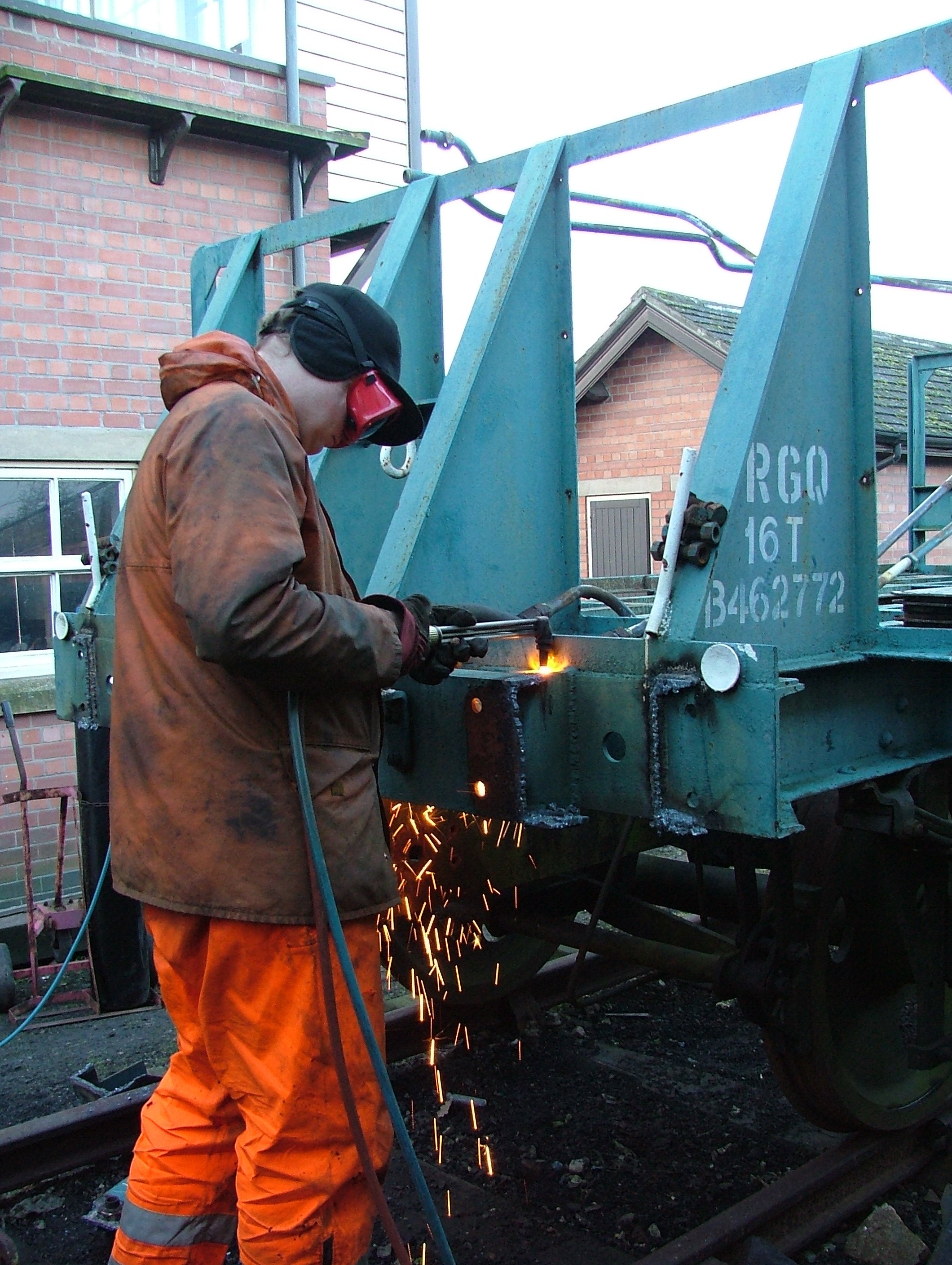 Photo © S. Sanders 15/01/06 |
Oxygen suitably replenished, a good day with the cutting gear saw both sides of the south end frame extension unceremoniously chopped off, although grinding and painting are required before the buffers can go back on. The middle portion of the frame extension has been left, just as at the north end, as some welding is required before the draw hook can be re-mounted in its original position. |
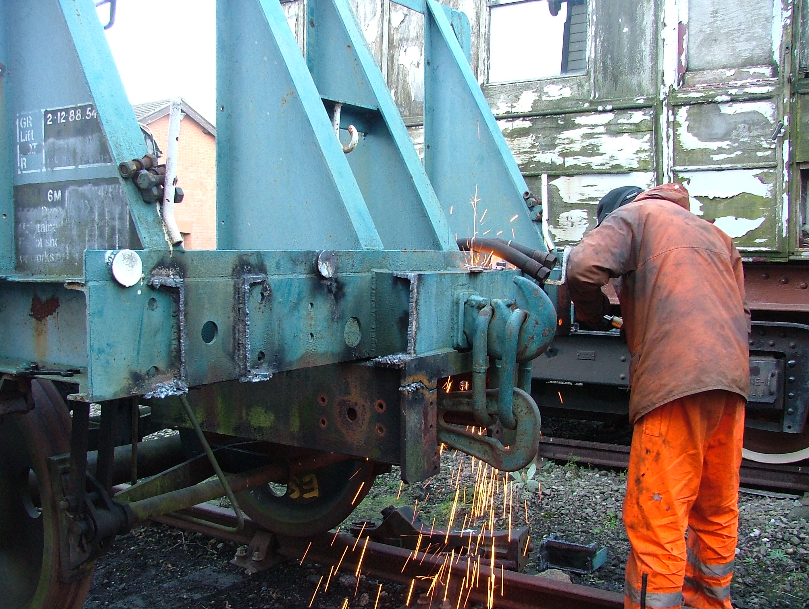 Photo © S. Sanders 15/01/06 |
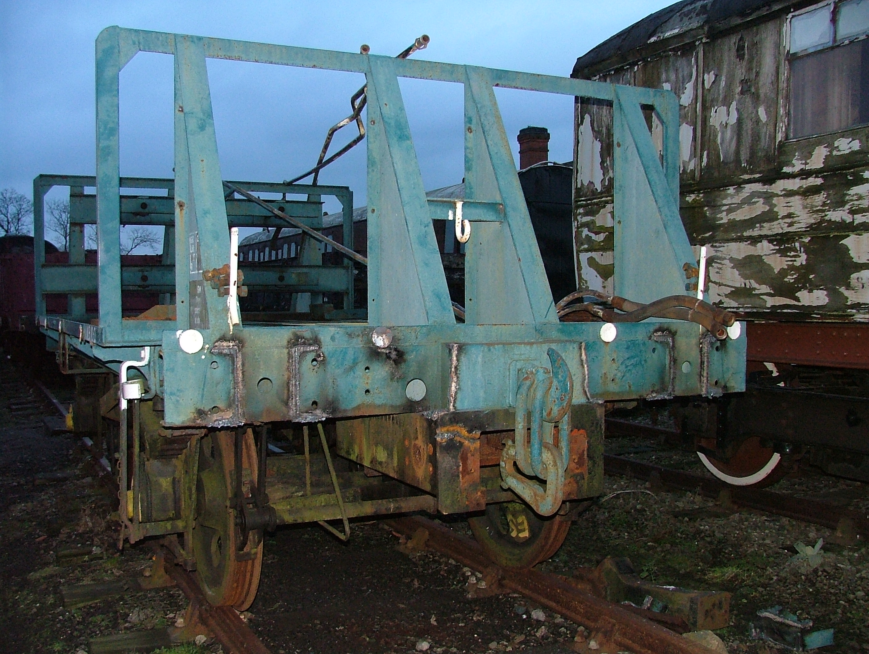 Photo © P. Hetherington 15/01/06 |
By the end of the day the south end looked like this (left). Incidently, the regulators on the cutting hoses came with some red plastic caps designed to keep the threads clean when not in use. Earlier in the day I'd put them on the solebar, but they kept blowing off (it was rather windy), so I moved them into a more sheltered corner - completely forgetting that I was heating up that corner of the wagon! The resulting mess (right) is all that remains of the two caps... |
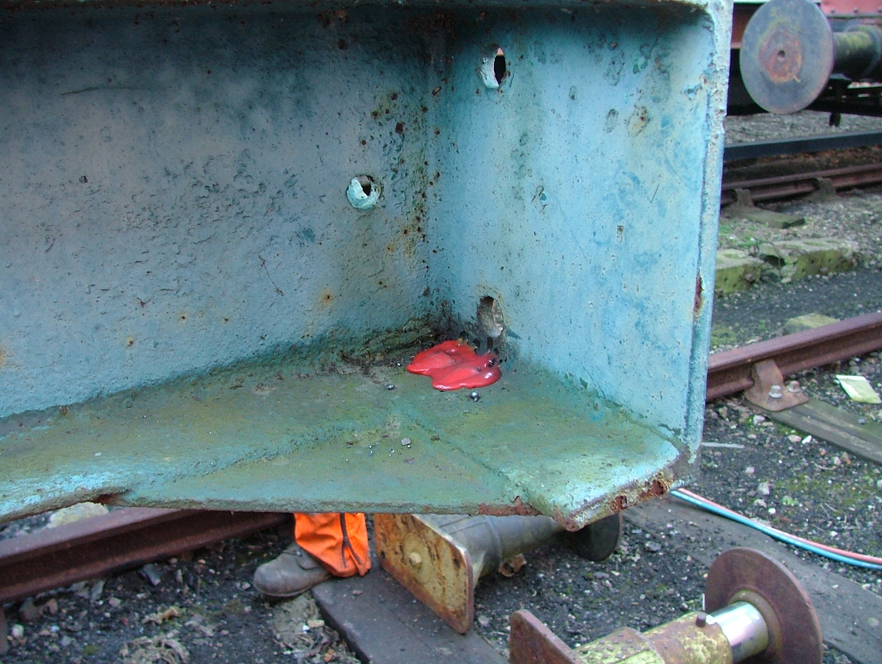 Photo © S. Sanders 15/01/06 |
 Photo © P. Hetherington 04/02/06 |
The day was spent angle-grinding the south end headstock in
preparation for the re-instatement of the buffers. We've found that
the best method is to run the cutting disc as close as possible to
the face of the headstock, before finishing off with the grinding
disc. In the event all four cuts were done, but only one of them was ground flush before bad light stopped play. Weather permitting, we'll continue with this job next weekend. |
Back to Part 2: May to August 2005
Go to Part 4: February to April 2006