
Photo © P. Hetherington 13/01/05.

Photo © P. Hetherington 13/01/05.

Photo © P. Hetherington 13/01/05.

Photo © P. Hetherington 13/01/05.
For a general history of the 'Palbrick' wagons please refer to the history page.
The last 'Palbrick B' wagons to be built were the 90 vehicles of lot 3243 built in late 1959 at Ashford, numbered from B462707 to B462796. These were the only 'Palbrick B' wagons built to diagram 1/026, which differed from earlier vehicles by using a more modern underframe with clasp brakes and roller bearings.
Although technically successful, the railways quickly lost the brick traffic to road competition and by the late 1960s many Palbrick wagons had fallen out of use. As relatively new vehicles, many were modified for other uses, including 55 of lot 3243 which became 'Freightliner match wagons' in 1967. B462772 was one of those converted.
Most of the other conversions were relatively short-lived, and by 2004 only a handful of Palbricks - probably less than ten, and all from the Freightliner conversions - were believed to survive. None had been preserved, the scale of the conversion probably being enough to put most people off. What was needed, clearly, was someone who fancied 'a bit of a challenge'...
B462772 ended its working life at Ipswich Wherstead Road depot, probably standing idle for a few years before being sold to a dealer in Norfolk when the yard closed for redevelopment in 2002. I purchased the wagon on 5 December 2004, and it moved to the Great Central Railway on 13 January 2005. Here our story begins...
A photograph of B462772 at its previous home in Norfolk appears here.
|
|
The wagon arrived by lorry in seven pieces, due to the loading
limit of the hi-ab crane. The wheels are on top of the wagon, but
sticking through the frame since there is currenly no floor. The
chap pictured is John Gatehouse who drove the lorry. Photo © P. Hetherington 13/01/05. |
|
|
First we unloaded the wheelsets, then the main body. We spun it
180° at this point (taking care not to mix up the wheelsets) to
ensure that the wagon is the best way round to gain access for
replacing the missing vacuum cylinder when the time comes. Thanks
are due to Nick Tinsley (pictured) for his assistance with
the unloading. Photo © P. Hetherington 13/01/05. |
|
|
The wagon was lowered onto its wheelsets one end at a time. Special
castings are used to allow roller bearings to fit a conventional
wagon underframe, and it was necessary to hold them to prevent them
from turning whilst guiding the underframe into position. Photo © P. Hetherington 13/01/05. |
|
|
...After which it looked like a wagon again, although I then had to
re-fit the straps which connect the bottom of the W-irons and
re-connect the hand brake before it could be declared mobile. Photo © P. Hetherington 13/01/05. |
 |
One of the works plates was missing when the wagon arrived. The
other one has now been removed too, and will be used to produce
a replica plate to replace the missing one. Photo © P. Hetherington 13/01/05. |
 |
The first part of the 'un-rebuilding' was the removal of the
air pipes which were added as part of the Freightliner conversion.
Freightliner wagons evidently have the air pipes routed through two
holes in the coupling, connected via flexible hoses. Photo © P. Hetherington 27/02/05. |
 |
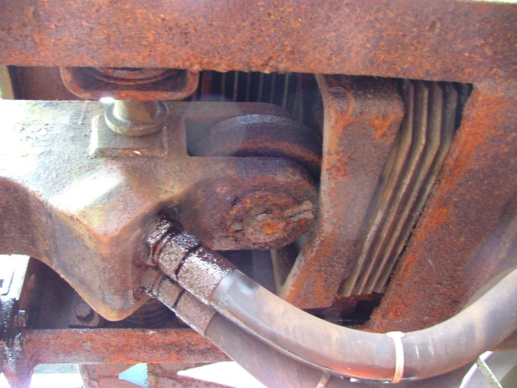
This means that an adaptor wagon actually needs four brake pipes, with
the two hoses on the headstocks at each end going to the
Freightliner coupling at the other end. This picture shows the left
hand pipes when viewed from beneath the wagon... Photo © P. Hetherington 27/02/05. |
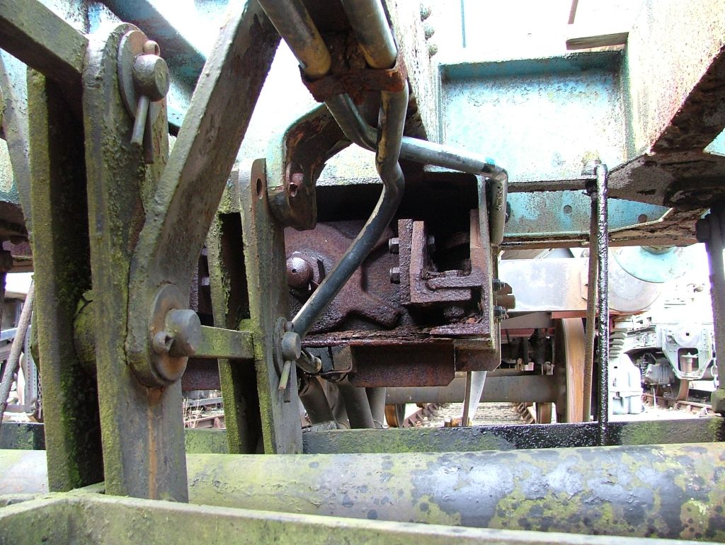 |
...and this picture shows the right hand pipes. The same pattern was
repeated at both ends of the wagon; this is the tensioning end (but
the coupling photographed above is the non-tensioning end). Photo © P. Hetherington 27/02/05. |
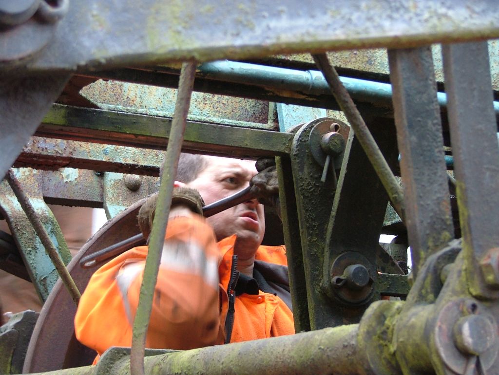 |
At this point I'd like to say thanks to Shawn Sanders (pictured left)
for helping with this task and for the use of his camera - which I
will now turn against him by suggesting this picture for a caption
competition! (My suggestion: "You've been framed!"). Photo © T. Vickery 27/02/05. |
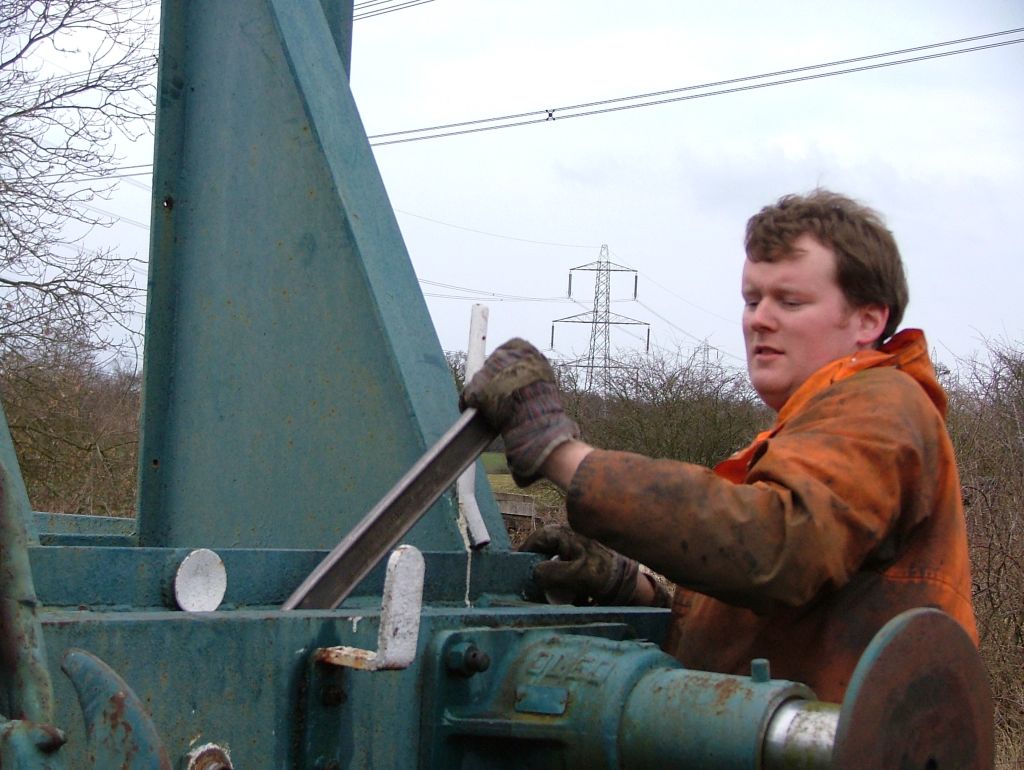 |
Finally, this picture shows me getting to grips with the air pipes
at the non-tensioning end and is included to prove that I didn't
just take photographs! Photo © T. Vickery (or maybe S. Sanders) 27/02/05. |
 |
Just below the buffer beam can be seen the large rectangular box which
houses one of the Freightliner couplings. These were added in about
1967 when the wagon was converted to an adaptor wagon, so they need
to be removed as part of the 'un-rebuilding' process. Photo © P. Hetherington 13/01/05. |
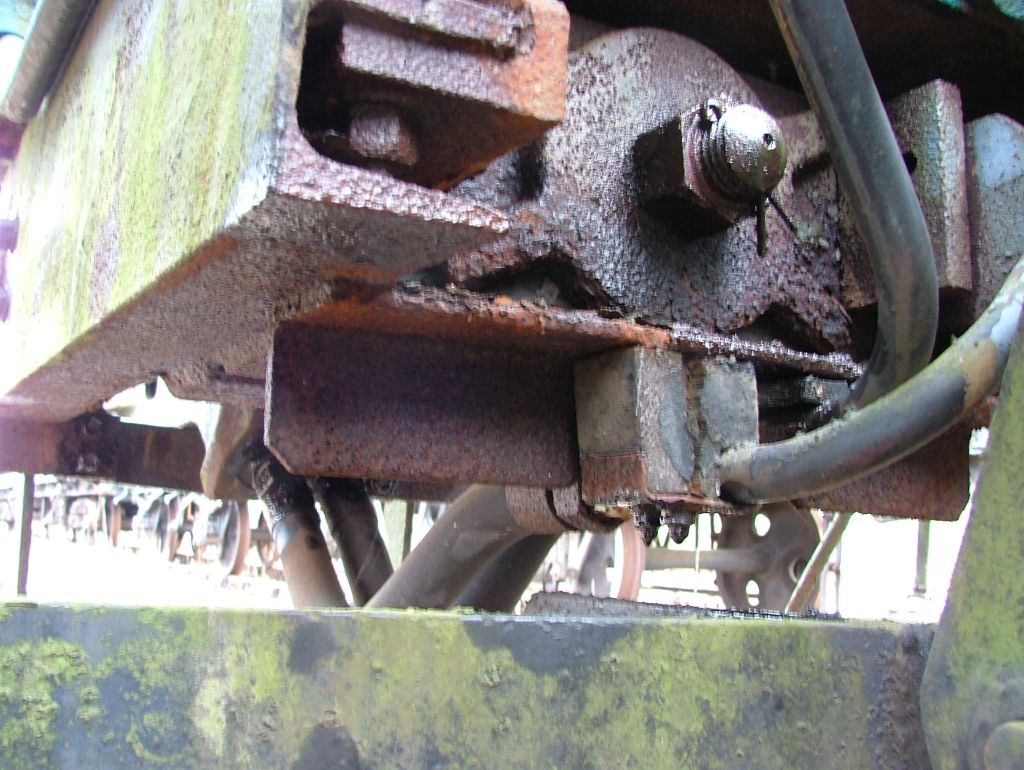 |
The first stage is to remove the large casting which sits inside the
box. This is held in place with a 2" Whitworth threaded nut
(2.75" across flats) which is extremely awkward to get to, being
recessed at the back of the box, between the frames. This photo shows
the south (non-tensioning) end, about which more later. Photo © P. Hetherington 27/02/05. |
 |
Working conditions are less than ideal. Shawn Sanders is seen removing
the split pin, probably from the south (non-tensioning) end after I had
given up in despair. I think the split pin at the south end took about
an hour of combined effort, although Shawn would probably say that it
would have been easier if I hadn't mangled it beyond all recognition
first! Photo © P. Hetherington 27/03/05. |
 |
The equivalent nut securing the north (tensioning) end coupling
actually came undone quite easily (thanks Shawn!), following which I
removed the strap from below the casting. This required the combined
efforts of an angle grinder and a large sledgehammer! The strap is
seen lying on the ground in this picture. Photo © P. Hetherington 27/03/05. |
 |
Following which we pulled it - or rather, bounced it up and down -
until it came out. Simple eh? You'll see from this picture that the
coupling is able to twist on its shaft, move laterally on its pivot
(restricted by small sprung 'buffers' within the housing), and is
damped longitudinally by a series of rectangular pads at the back.
There is some vertical movement too as the whole assemply is slightly
'loose'; I presume this is intentional. Photo © P. Hetherington 27/03/05. |
 |
Next we thought we'd remove one of the small buffers from the
coupler housing, using of course the 'brute force and ignorance'
method (i.e. angle grinder) which made for spectacular photographs
if nothing else. They are secured with four bolts and a metal chock,
and the action of the spring ensures that this is NOT the correct
method as the pin simply tightens against the chock. We got there
eventually, but for the next one we'll try jacking against the
inside to compress the spring. Watch this space. Photo © P. Hetherington 27/03/05. |
 |
Attention now turned to the south end couplling. On the previous
visit we'd established that the nut wasn't going to come undone easily,
so this time I borrowed a large socket set from Loughborough loco shed
(thanks!). The first thing I tried was to soak the nut in oil, which made a mess but didn't help much. So I tried heating it up with a blowlamp, but still no movement. Then I put an extension on the socket set to give a six-foot lever, and tried pulling it as hard as I dared with the nut still hot. It still wouldn't budge. Time for a change of tactic I thought, so I tried sitting underneath the wagon with my back to the wheel and pushing the lever with my feet. Nothing. Next I tried jacking the handle up off the ground with a 2 tonne jack. The nut still refused to budge, but I did manage to rotate the entire casting about 15 degrees. Photo © P. Hetherington 10/04/05. |
 |
This gave me a brainwave, so I tried jamming the handle against the
frame of the wagon, whilst putting a crowbar through a hole in the side
of the coupling and standing on it. Result: the crowbar started to bend!
I think it was at around this point that I decided that the nut might
not want to come off in one piece... So it was back to the trusty angle grinder, with which I completely sliced off one side of the nut so that it was now C-shaped, and would you believe that it STILL would not budge! So, after seven hours work, I had removed about 1/3 of a single nut and was not much closer to getting the coupling off than when I started. Well, nobody said it was going to be easy... Photo © P. Hetherington 10/04/05. |
 Photo © A. Basset 30/04/05. |
Continuing where I left off, the nut holding the south end coupling had another piece sliced off the opposite site, leaving just pieces at the top and bottom to be knocked off with a hammer. Even then they put up a fight! |
 Photo © P. Hetherington 30/04/05. |
 Photo © A. Basset 30/04/05. |
When the final piece eventually gave way, the entire coupling sprang outwards by a couple of inches, thus revealing why the nut had been impossible to undo - it was held tight by the massive tension in the coupling. |
 Photo © P. Hetherington 30/04/05. |
Go to Part 2: May to August 2005